Stimuli provider (Environment)
Introduction
The database section must feed a stimuli provider (or environment), which is
instantiated with a section named sp (or env) in the INI file. When the
two sections are present in the INI file, they are implicitly connected: the
StimuliProvider is automatically aware of the Database driver that is
present. The StimuliProvider section specifies the input dimensions of the
network (width, height), as well as the batch size.
Example:
[sp]
SizeX=24
SizeY=24
BatchSize=12 ; [default: 1]
Data augmentation and conditioning Transformation blocks and data analysis
StimuliData blocks can be associated to a stimuli provider as shown below:
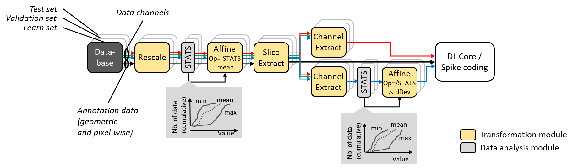
Data augmentation, conditioning and analysis flow.
The table below summarizes the parameters available for the sp section:
Option [default value] |
Description |
|---|---|
|
Environment width |
|
Environment height |
|
Number of channels (applicable only if there is no |
|
Batch size |
|
If true, use pixel-wise stimuli labels |
|
Stimuli cache path (no cache if left empty) |
The env section accepts more parameters dedicated to event-based (spiking)
simulation:
Option ( |
Description |
|---|---|
|
Method for converting stimuli into spike trains. Can be any of |
|
The pixels in the pre-processed stimuli with a value above this limit never generate spiking events |
|
Mean minimum period \(\overline{T_{min}}\), used for periodic temporal codings, corresponding to pixels in the pre-processed stimuli with a value of 0 (which are supposed to be the most significant pixels) |
|
Mean maximum period \(\overline{T_{max}}\), used for periodic temporal codings, corresponding to pixels in the pre-processed stimuli with a value of 1 (which are supposed to be the least significant pixels). This maximum period may be never reached if |
|
Relative standard deviation, used for periodic temporal codings, applied to the spiking period of a pixel |
|
Absolute minimum period, or spiking interval, used for periodic temporal codings, for any pixel |
For image segmentation, the parameter CompositeStimuli=1 must always be
present, meaning that the labels of the image must have the same dimension than
the image (and cannot be a single class value as in classification problem).
Data range and conversion
A configuration section can be associated to a StimuliProvider, as shown
below. The DataSignedMapping=1 parameter specifies that the input value
range must be interpreted as signed, even if the values are unsigned, which is
usually the case for standard image formats (BMP, JPEG, PNG…). In case of
8-bit images, values from 0 to 255 are therefore mapped to the range -128 to
127 when this parameter is enabled.
[sp]
SizeX=[database.slicing]Width
SizeY=[database.slicing]Height
BatchSize=${BATCH_SIZE}
CompositeStimuli=1
ConfigSection=sp.config

[sp.config]
DataSignedMapping=1
Note
In N2D2, the integer value input range [0, 255] (or [-128, 127] with the
DataSignedMapping=1 parameter) (for 8-bit images), is implicitly converted to
floating point value range [0.0, 1.0] or [-1.0, 1.0] in the StimuliProvider,
after the transformations, unless one of the transformation changes the
representation and/or the range of the data.
Note
The DataSignedMapping parameter only has effect when implicit conversion
is performed.
The input value range can also be changed explicitly using for example a
RangeAffineTransformation, like below, in which case no implicit conversion
is performed afterwards (and the DataSignedMapping parameter has no effect):
[sp.Transformation-rangeAffine]
Type=RangeAffineTransformation
FirstOperator=Minus
FirstValue=128.0
SecondOperator=Divides
SecondValue=128.0
When running a simulation in N2D2, the graph of the transformations with all their parameters as well as the expected output dimension after each transformation is automatically generated (in the file transformations.png). As transformations can be applied only to one of the learn, validation or test datasets, three graphs are generated, as shown in the following figure.
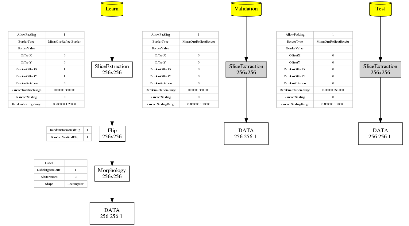
Graph of the transformations for the learn, validation and test datasets, automatically generated by N2D2.
Images slicing during training and inference
In N2D2, the input dimensions of a neural network is fixed and cannot be changed dynamically during the training and inference, as images are processed in batch, like any other deep learning framework. Therefore, in order to deal with datasets containing images of variable dimensions, patches or slices of fixed dimensions must be extracted.
In N2D2, two mechanisms are provided to extract slices:
For training, random slices can be extracted from bigger images for each batch, thus allowing to cover the full images over the training time with the maximum variability. This also act as basic data augmentation. Random slices extraction is achieved using a
SliceExtractionTransformation, applied only to the training set with the parameterApplyTo=LearnOnly.
[sp.OnTheFlyTransformation-1]
Type=SliceExtractionTransformation
Width=${WIDTH}
Height=${HEIGHT}
RandomOffsetX=1
RandomOffsetY=1
AllowPadding=1
ApplyTo=LearnOnly
For inference, one wants to cover the full images once and only once. This cannot be achieved with a N2D2
Transformation, but has to be handled by theDatabasedriver. In order to do so, anyDatabasedriver can have an additional “slicing” section in the N2D2 INI file, which will automatically extract regularly strided fixed size slices from the dataset. The example above can be used to extract slides for the validation and testing datasets, with the parameterApplyTo=NoLearn.
[database.slicing]
Width=${WIDTH}
Height=${HEIGHT}
StrideX=[database.slicing]Width
StrideY=[database.slicing]Height
Overlapping=1
ApplyTo=NoLearn
When an image size is not a multiple of the slices size, the most right and
most bottom slices may have a size lower than the intended fixed slice size
specified with Width and Height. There are two ways to deal with these slices:
Add the
Overlapping=1parameter, which allows an overlapping between the right/bottom-most slice and the preceding one. The overlapping area in the right/bottom-most slice is then marked as “ignore” for the labeling, to avoid counting twice the classification result on these pixels.Add a
PadCropTransformationto pad to the slice target size forNoLearndata. In this case the padded area can be either ignored or mirror padding can be used.
Blending for data augmentation
Complex data augmentation / pre-processing pipelines can be created by combining
the different available transformations. It is even possible to use multiple
Database and StimuliProvider, to create for example a “blending” pipeline,
which is introduced here and illustrated in the figure below.
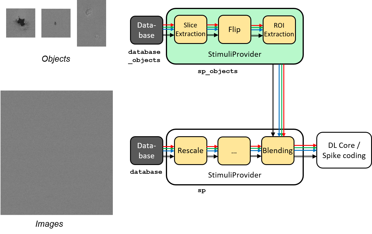
Blending pipeline working principle.
An example of a blending pipeline in the INI file is given here. The first part
is the BlendingTransformation, which is inserted in the main image processing
pipeline.
...

; Here we add a blending transformation, which will perform objects blending
; to images with the specified labels in the dataset, selected by the
; ApplyToLabels parameter.
[sp.OnTheFlyTransformation-blend]
Type=BlendingTransformation
ApplyTo=LearnOnly
Database=database_objects ; database driver to use for the objects to blend
StimuliProvider=sp_objects  ; stimuli provider specifying the transformations
                            ; to apply on the object data before blending
; Specifies the name of the image label(s) on which a blending can be performed.
; Here, any image in a "backgrounds" sub-directory in the dataset will be used
; for the blending
; POSSIBLE FUTURE EXTENSION: possibility to associate some backgrounds to some
; object types only. Adding a background in a "backgrounds" sub-directory in the
; object directory may allow this.
; POSSIBLE FUTURE EXTENSION: specify ROIs for blending some object types.
ApplyToLabels=*backgrounds*
; Indicate whether multiple object types can be mixed on the same background
TypeMixing=0
; Density of the object in the background, from 0.0 to 1.0
DensityRange=0.0 0.2
; Horizontal margin between objects (in pixels)
MarginH=0
; Vertical margin between objects (in pixels)
MarginV=0
; Blending method
; POSSIBLE FUTURE EXTENSION: add other blending methods...
BlendingMethod=SmoothEdge
BlendingSmoothSize=5
; For DEBUG purpose, specifying a non-empty SavePath will save all the generated
; blending with their associated JSON annotation in the SavePath directory.
SavePath=blending

...
The second part is the object pre-processing and extraction pipeline, that is
attached to the BlendingTransformation.
; --- BEGIN --- DATA TO BLEND PRE-PROCESSING ---
; Database driver for the objects. Can be a sub-set of the main pipe image
; dataset, or even the full main dataset itself
[database_objects]
Type=DIR_Database
DataPath=${DATA_PATH}
Depth=-1
LabelDepth=1
Learn=1.0
EquivLabelPartitioning=0
; Since we use the same dataset, ignore the background images that contain
; no object to blend.
IgnoreMasks=*backgrounds*
DefaultLabel=background ; Label for pixels outside any ROI (default is no label, pixels are ignored)

; Simuli provider for objects => no need to change this part.
[sp_objects]
; Sizes to 0 means any size, require that BatchSize=0
SizeX=0
SizeY=0
BatchSize=0

; Apply random rotation & scaling to objects
; POSSIBLE FUTURE EXTENSION: apply different transformations depending on the
; type of object
[sp_objects.OnTheFlyTransformation-0]
Type=SliceExtractionTransformation
; Sizes to 0 means any size, size will not be changed by the transformation
Width=0
Height=0
RandomRotation=1
RandomScaling=1
RandomScalingRange=0.5 2.0

; ... add here other transformations to apply to objects before extraction and
; blending

; Extend the object labels to have a smooth transition with background
[sp_objects.OnTheFlyTransformation-1]
Type=MorphologyTransformation
Operation=Dilate
Size=3
ApplyToLabels=1
NbIterations=2

; This has to be the last transformation in the pre-processing of the images
; that will be blended.
; After data augmentation, a random object is extracted from the image,
; using ROIs or connected-component labeling.
[sp_objects.OnTheFlyTransformation-2]
Type=ROIExtractionTransformation
; Extract any label ID
Label=-1
; Perform connected-component labeling to the label to obtain objects ROIs.
LabelSegmentation=1
Margin=0
KeepComposite=1
; Possibility to filter the ROIs to keep before random selection of a single
; one:
MinSize=0
FilterMinHeight=0
FilterMinWidth=0
FilterMinAspectRatio=0.0
FilterMaxAspectRatio=0.0
MergeMaxHDist=10
MergeMaxVDist=10
; --- END --- DATA TO BLEND PRE-PROCESSING ---
Built-in transformations
There are 6 possible categories of transformations:
env.Transformation[...]Transformations applied to the input images before channels creation;env.OnTheFlyTransformation[...]On-the-fly transformations applied to the input images before channels creation;env.ChannelTransformation[...]Create or add transformation for a specific channel;env.ChannelOnTheFlyTransformation[...]Create or add on-the-fly transformation for a specific channel;env.ChannelsTransformation[...]Transformations applied to all the channels of the input images;env.ChannelsOnTheFlyTransformation[...]On-the-fly transformations applied to all the channels of the input images.
Example:
[env.Transformation]
Type=PadCropTransformation
Width=24
Height=24
Several transformations can applied successively. In this case, to be
able to apply multiple transformations of the same category, a different
suffix ([...]) must be added to each transformation.
The transformations will be processed in the order of appearance in the INI file regardless of their suffix.
Common set of parameters for any kind of transformation:
Option [default value] |
Description |
|---|---|
|
Apply the transformation only to the specified stimuli sets. Can be: |
|
|
|
|
|
|
|
|
|
|
|
|
|
Example:
[env.Transformation-1]
Type=ChannelExtractionTransformation
CSChannel=Gray

[env.Transformation-2]
Type=RescaleTransformation
Width=29
Height=29

[env.Transformation-3]
Type=EqualizeTransformation

[env.OnTheFlyTransformation]
Type=DistortionTransformation
ApplyTo=LearnOnly ; Apply this transformation for the Learning set only
ElasticGaussianSize=21
ElasticSigma=6.0
ElasticScaling=20.0
Scaling=15.0
Rotation=15.0
List of available transformations:
AffineTransformation
Apply an element-wise affine transformation to the image with matrixes of the same size.
Option [default value] |
Description |
|---|---|
|
First element-wise operator, can be |
|
First matrix file name |
|
Second element-wise operator, can be |
|
Second matrix file name |
The final operation is the following, with \(A\) the image matrix, \(B_{1st}\), \(B_{2nd}\) the matrixes to add/substract/multiply/divide and \(\odot\) the element-wise operator :
ApodizationTransformation
Apply an apodization window to each data row.
Option [default value] |
Description |
|---|---|
|
Window total size (must match the number of data columns) |
|
Window name. Possible values are: |
|
|
|
|
|
|
|
|
|
|
|
|
|
Gaussian window
Gaussian window.
Option [default value] |
Description |
|---|---|
WindowName |
Sigma |
Blackman window
Blackman window.
Option [default value] |
Description |
|---|---|
WindowName |
Alpha |
Kaiser window
Kaiser window.
Option [default value] |
Description |
|---|---|
WindowName |
Beta |
CentroidCropTransformation
Find the centroid of the image and crop the image so that the center of the image
matches the centroid location. The cropping can be done on both axis, or just
one axis with the Axis parameter. If Axis is 1, only the horizontal axis
will be cropped so that the centroid x-location is at half the image width.
Option [default value] |
Description |
|---|---|
|
Axis to consider for the centroid (-1 = both, 0 = cols, 1 = rows) |
In practice, this transformation can be used in conjunction with the
PadCropTransformation, in order to obtain cropped images of always of the same
dimension (by cropping for example to the smallest image obtained after
CentroidCropTransformation), all centered on their respective centroid.
BlendingTransformation
N2D2-IP only: available upon request.
This transformation can be used to blend image objects, provided by another
Database and associated StimuliProvider, to the images of the current
StimuliProvider.
Option [default value] |
Description |
|---|---|
|
Name of the |
|
Name of the |
|
Space-separated list that specifies the name of the image label(s) on which a blending can be performed (in the current data pipe). The usual * and + wildcards are allowed. |
|
If true (1), multiple object types can be mixed on the same image |
|
Range of density of the objects to blend in the image (values are from 0.0 to 1.0). A different random density in this range is used for each image. If the two values are equal, the density is constant. A constant density of 0 (corresponding the default range [0.0 0.0]) means that only a single object is blended in the image in all cases, regardless of the object size. Indeed, the density parameter is checked only after the first object was inserted. |
|
Minimum horizontal margin between inserted objects (in pixels) |
|
Minimum vertical margin between inserted objects (in pixels) |
|
Blending method to use (see the |
|
\(\alpha\) factor for the blending. Depends on the blending method (see the |
|
\(\beta\) factor for the blending. Depends on the blending method (see the |
|
Blurring kernel size, used in some blending methods (see the |
|
If not empty, all the blended images are stored in |
BlendingMethod
In the following equations, \(O\) is the object image, \(I\) is the image of the current pipe on which objects must be inserted. And \(R\) is the resulting image.
Linear: no smoothing.\(R=\alpha.O + \beta.I\)
LinearByDistance: limit the blur in the blended object background.- \(\Delta = \frac{\|O-I\|-min(\|O-I\|)}{max(\|O-I\|)-min(\|O-I\|)}\)\(R=\alpha.O.(1-\Delta) + \beta.I.\Delta\)
SmoothEdge: smoothing at the borders of the objects.- \(\alpha = \begin{cases} 1 & \text{when } LABEL \neq 0\\ 0 & \text{otherwise} \end{cases}\)\(\alpha' = gaussian\_blur(\alpha)\)\(R=\alpha'.O + (1-\alpha').I\)
SmoothEdgeLinearByDistance: combinesSmoothEdgeandLinearByDistance.- \(\alpha = \begin{cases} \Delta & \text{when } LABEL \neq 0\\ 0 & \text{otherwise} \end{cases}\)\(\alpha' = gaussian\_blur(\alpha)\)\(R=\alpha'.O + (1-\alpha').I\)
Labels mapping
When processing the first batch of data, you might get a message like the following in the console:
BlendingTransformation: labels mapping is required with the following mapping:
  1 -> 9   (cat)
  2 -> 12   (dog)
  3 -> 66   (bird)
What happens here is that the labels ID from the database containing the objects
to blend (specified by the Database parameter) must match the correct labels
ID from the current database (specified by the [database] section).
In the log above, the labels ID on the left are the ones from the objects
database and the labels ID on the right are the ones from the current database.
In N2D2, upon loading a database, a new label ID is created for each new unique
label name encoutered, in the loading order (alphabetical for DIR_Database,
but may be arbitrary for other database drivers). The objects database may
contain only a subset of the labels present in the current database,
and/or the labels may be loaded in a different order. In both cases, the ID
affected to a label name will be different between the two databases. During
blending however, one wants that the blended object labels correspond to the
labels of the current database. To solve this, labels mapping is automatically
performed in N2D2 so that for corresponding label names, the label
ID in the objects database is translated to the label ID of current database.
In the log above for example, the objects database contains only 3 labels:
“cat”, “dog” and “bird”, with ID 1, 2 and 3 respectively. These
labels ID are automatically replaced by the corresponding ID (for identical
label name) in the current database, for the blended objects, which are here
9, 12 and 66 respectively.
Note
Each label from the objects database (objects to blend) must match an existing label in the current database. There is a match if:
There is an identical label name in the current database;
There is a single label name in the current database that ends with the objects database label name. For example, the label “/dog” in the objects database will match with the “dog” label in the current database.
If the objects database contains a label name that does not exist/match in the current database, an error is emitted:
BlendingTransformation: label "xxx" in blending database not present in current database!
ChannelDropTransformation
N2D2-IP only: available upon request.
Randomly drop some channels of the image and replace them with a constant value. This can be useful to simulate missing channel data in multi-channel data.
Option [default value] |
Description |
|---|---|
|
Channel’s drop probabilities (space-separated list of probabilities, in the order of the image channels) |
|
Value to use for dropped channels pixels |
ChannelExtractionTransformation
Extract an image channel.
Option |
Description |
|---|---|
|
|
|
|
|
|
|
|
|
|
|
|
|
|
|
|
|
|
|
ChannelShakeTransformation
N2D2-IP only: available upon request.
Randomly shift some channels of the image. This can be useful to simulate misalignment between multiple channel data.
Option [default value] |
Description |
|---|---|
|
Vertical shift range (in pixels) for each channel. For example, to randomly shift the second channel by +/- 5
pixels in the vertical direction, use: |
|
Horizontal shift range (in pixels) for each channel |
|
Random distribution to use for the shift |
|
If true (1), use integer value for the shifts (no pixel interpolation needed) |
|
Border type used when padding. Possible values: |
[ |
|
|
|
|
|
|
|
|
|
|
|
|
Background color used when padding with |
Distribution
Possible distribution and meaning of the range.
For example with VerticalRange[1]=-5.0 5.0.
UniformUniform between -5 and 5.
NormalNormal with mean (-5+5)/2=0 and std. dev. = (5-(-5))/6 = 1.67. The range defines the std. dev. such that range = 6 sigma.
TruncatedNormalSame as
Normal, but truncated between -5 and 5.
ColorSpaceTransformation
Change the current image colorspace.
Option |
Description |
|---|---|
|
|
|
|
|
|
|
|
|
|
|
|
|
|
|
|
|
|
|
|
|
|
|
|
|
|
|
|
|
|
|
|
|
|
|
|
|
|
|
|
|
|
|
|
|
Note that the default colorspace in N2D2 is BGR, the same as in OpenCV.
DFTTransformation
Apply a DFT to the data. The input data must be single channel, the resulting data is two channels, the first for the real part and the second for the imaginary part.
Option [default value] |
Description |
|---|---|
|
If true, compute a 2D image DFT. Otherwise, compute the 1D DFT of each data row |
Note that this transformation can add zero-padding if required by the underlying FFT implementation.
DistortionTransformation
Apply elastic distortion to the image. This transformation is generally used on-the-fly (so that a different distortion is performed for each image), and for the learning only.
Option [default value] |
Description |
|---|---|
|
Size of the gaussian for elastic distortion (in pixels) |
|
Sigma of the gaussian for elastic distortion |
|
Scaling of the gaussian for elastic distortion |
|
Maximum random scaling amplitude (+/-, in percentage) |
|
Maximum random rotation amplitude (+/-, in °) |
EqualizeTransformation
Image histogram equalization.
Option [default value] |
Description |
|---|---|
|
|
|
|
|
Threshold for contrast limiting (for |
|
Size of grid for histogram equalization (for |
ExpandLabelTransformation
Expand single image label (1x1 pixel) to full frame label.
FilterTransformation
Apply a convolution filter to the image.
Option [default value] |
Description |
|---|---|
|
Convolution kernel. Possible values are: |
|
|
|
|
|
|
|
|
|
* kernel
Custom kernel.
Option |
Description |
|---|---|
|
Width of the kernel (numer of columns) |
|
Height of the kernel (number of rows) |
|
List of row-major ordered coefficients of the kernel |
If both Kernel.SizeX and Kernel.SizeY are 0, the kernel is
assumed to be square.
Note
When providing a custom kernel, no normalization is applied on its coefficients.
Gaussian kernel
Gaussian kernel.
Option [default value] |
Description |
|---|---|
|
Width of the kernel (numer of columns) |
|
Height of the kernel (number of rows) |
|
If true, the center of the kernel is positive |
|
Sigma of the kernel |
LoG kernel
Laplacian Of Gaussian kernel.
Option [default value] |
Description |
|---|---|
|
Width of the kernel (numer of columns) |
|
Height of the kernel (number of rows) |
|
If true, the center of the kernel is positive |
|
Sigma of the kernel |
DoG kernel
Difference Of Gaussian kernel kernel.
Option [default value] |
Description |
|---|---|
|
Width of the kernel (numer of columns) |
|
Height of the kernel (number of rows) |
|
If true, the center of the kernel is positive |
|
Sigma1 of the kernel |
|
Sigma2 of the kernel |
Gabor kernel
Gabor kernel.
Option [default value] |
Description |
|---|---|
|
Width of the kernel (numer of columns) |
|
Height of the kernel (number of rows) |
|
Theta of the kernel |
|
Sigma of the kernel |
|
Lambda of the kernel |
|
Psi of the kernel |
|
Gamma of the kernel |
FlipTransformation
Image flip transformation.
Option [default value] |
Description |
|---|---|
|
If true, flip the image horizontally |
|
If true, flip the image vertically |
|
If true, randomly flip the image horizontally |
|
If true, randomly flip the image vertically |
GradientFilterTransformation
Compute image gradient.
Option [default value] |
Description |
|---|---|
|
Scale to apply to the computed gradient |
|
Bias to add to the computed gradient |
|
Filter type to use for computing the gradient. Possible options are: |
|
Size of the filter kernel (has no effect when using the |
|
If true, use the computed gradient to filter the image label and ignore pixel areas where the gradient is below the |
|
If true, ignored label pixels will be the ones with a low gradient (low contrasted areas) |
|
Threshold applied on the image gradient |
|
List of labels to filter (space-separated) |
|
Rescale the image by this factor before applying the gradient and the threshold, then scale it back to filter the labels |
LabelFilterTransformation
Filter labels in the image. The specified labels can be removed, kept (meaning all the other labels removed), or merged (the specified labels are replace by the first one).
Option [default value] |
Description |
|---|---|
|
Space-separated list of label names to be filtered |
|
Type of filter to apply: |
|
Default label, to be used where labels are removed. With the default value (-2), the default label of the associated database is used. If there is no default label, -1 (ignore) is used |
This transformation filters both pixel-wise labels and ROIs.
LabelSliceExtractionTransformation
Extract a slice from an image belonging to a given label.
Option [default value] |
Description |
|---|---|
|
Width of the slice to extract |
|
Height of the slice to extract |
|
Slice should belong to this label ID. If -1, the label ID is random |
|
If true, extract randomly rotated slices |
|
Range of the random rotations, in degrees, counterclockwise (if |
|
Positive or negative, indicates the margin around objects that can be extracted in the slice |
|
If false, the 2D label image is reduced to a single value corresponding to the extracted object label (useful
for patches classification tasks). Note that if |
|
If true, zero-padding is allowed if the image is smaller than the slice to extract |
|
Border type used when padding. Possible values: |
|
|
|
|
|
|
|
|
|
|
|
|
|
Background color used when padding with |
|
If true (1), if no valid slice is found, a random slice is extracted and marked as ignored (-1) |
|
Space-separated list of label ID to exclude from the random extraction (when |
This transformation is useful to learn sparse object occurrences in a lot of background. If the dataset is very unbalanced towards background, this transformation will ensure that the learning is done on a more balanced set of every labels, regardless of their actual pixel-wise ratio.
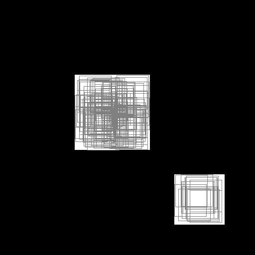
Illustration of the working behavior of LabelSliceExtractionTransformation
with SlicesMargin = 0:
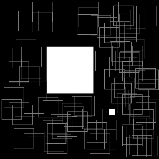
Randomly extracted slices with label 0.
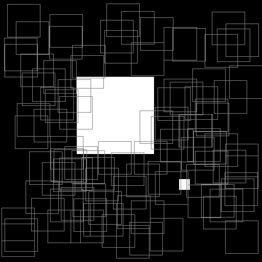
Randomly extracted slices with label 1.
When SlicesMargin is 0, only slices that fully include a given label
are extracted, as shown in figures above. The behavior with
SlicesMargin < 0 is illustrated in figures below. Note that setting a negative
SlicesMargin larger in absolute value than Width/2 or
Height/2 will lead in some (random) cases in incorrect slice labels
in respect to the majority pixel label in the slice.
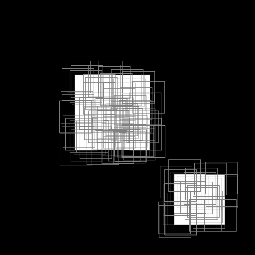
Illustration of the working behavior of LabelSliceExtractionTransformation
with SlicesMargin = -32:
Randomly extracted slices including label 0.
Randomly extracted slices including label 1.
MagnitudePhaseTransformation
Compute the magnitude and phase of a complex two channels input data, with the first channel \(x\) being the real part and the second channel \(y\) the imaginary part. The resulting data is two channels, the first one with the magnitude and the second one with the phase.
Option [default value] |
Description |
|---|---|
|
If true, compute the magnitude in log scale |
The magnitude is:
If LogScale = 1, compute \(M'_{i,j} = log(1 + M_{i,j})\).
The phase is:
MorphologicalReconstructionTransformation
Apply a morphological reconstruction transformation to the image. This transformation is also useful for post-processing.
Option [default value] |
Description |
|---|---|
|
Morphological operation to apply. Can be: |
|
|
|
|
|
|
|
|
|
Size of the structuring element |
|
If true, apply the transformation to the labels instead of the image |
|
Shape of the structuring element used for morphology operations. Can be |
|
Number of times erosion and dilation are applied for opening and closing reconstructions |
MorphologyTransformation
Apply a morphology transformation to the image. This transformation is also useful for post-processing.
Option [default value] |
Description |
|---|---|
|
Morphological operation to apply. Can be: |
|
|
|
|
|
|
|
|
|
|
|
|
|
|
|
Size of the structuring element |
|
If true, apply the transformation to the labels instead of the image |
|
Shape of the structuring element used for morphology operations. Can be |
|
Number of times erosion and dilation are applied |
NormalizeTransformation
Normalize the image.
Option [default value] |
Description |
|---|---|
|
Norm type, can be: |
|
|
|
|
|
|
|
|
|
Norm value (for |
Such that \(||data||_{L_{p}} = NormValue\) |
|
|
Min value (for |
Such that \(min(data) = NormMin\) |
|
|
Max value (for |
Such that \(max(data) = NormMax\) |
|
|
If true, normalize each channel individually |
PadCropTransformation
Pad/crop the image to a specified size.
Option [default value] |
Description |
|---|---|
|
Width of the padded/cropped image |
|
Height of the padded/cropped image |
|
Border type used when padding. Possible values: |
|
|
|
|
|
|
|
|
|
|
|
|
|
Background color used when padding with |
ROIExtractionTransformation
The transformation is typically used as the last transformation of the object
extraction pipeline to be used for blending in a BlendingTransformation.
A random object of with the label Label is extracted from the image.
Option [default value] |
Description |
|---|---|
|
Label ID to extract (-1 means any label ID) |
|
If true (1), perform connected-component labeling to the label to obtain object ROIs |
|
Margin to keep around the object (in pixels) |
|
If true (1), the extracted object label remains composite. Otherwise, the label is reduced to a single value |
When LabelSegmentation is 0, this transformation directly extracts one of
the annotation ROI whose label matches Label. When LabelSegmentation is
true (1), the annotation ROIs are not used directly. Rather, the flattened
pixel-wise annotation is (re-)labeled using connected-component labeling to
obtain ROIs to extract. Note that the annotation ROIs are part of the
flattened pixel-wise annotation (see also the Database CompositeLabel
parameter).
Additional parameters for ROI filtering, before random selection of a single one:
Parameter |
Default value |
Description |
|---|---|---|
|
0 |
Minimum number of pixels than can constitute a bounding box.
Bounding boxes with fewer than |
|
0 |
Minimum height of the ROI to keep it |
|
0 |
Minimum width of the ROI to keep it |
|
0.0 |
Minimum aspect ratio (width/height) of the ROI to keep it (default is 0.0 = no minimum) |
|
0.0 |
Maximum aspect ratio (width/height) of the ROI to keep it (default is 0.0 = no minimum) |
|
1 |
Maximum horizontal distance for merging (in pixels) |
|
1 |
Maximum vertical distance for merging (in pixels) |
Note that these parameters applies only when LabelSegmentation is true (1).
RandomAffineTransformation
Apply a global random affine transformation to the values of the image.
Option [default value] |
Description |
|---|---|
|
Random gain (\(\alpha\)) range (identical for all channels) |
|
Random gain (\(\alpha\)) range for channel |
The gain control the contrast of the image |
|
|
Random bias (\(\beta\)) range (identical for all channels) |
|
Random bias (\(\beta\)) range for channel |
The bias control the brightness of the image |
|
|
Random gamma (\(\gamma\)) range (identical for all channels) |
|
Random gamma (\(\gamma\)) range for channel |
The gamma control more or less the exposure of the image |
|
|
Probability to have a gain variation for each channel. If only one value is specified, the same probability applies to all the channels. In this case, the same gain variation will be sampled for all the channels only if a single range if specified for all the channels using |
|
Probability to have a bias variation for each channel. If only one value is specified, the same probability applies to all the channels. In this case, the same bias variation will be sampled for all the channels only if a single range if specified for all the channels using |
|
Probability to have a gamma variation for each channel. If only one value is specified, the same probability applies to all the channels. In this case, the same gamma variation will be sampled for all the channels only if a single range if specified for all the channels using |
|
If true, gamma variation and gain/bias variation are mutually exclusive. The probability to have a random gamma variation is therefore |
|
If not empty, specifies on which channels the transformation is applied. For example, to apply the transformation only to the first and third channel, set |
The equation of the transformation is:
RangeAffineTransformation
Apply an affine transformation to the values of the image.
Option [default value] |
Description |
|---|---|
|
First operator, can be |
|
First value |
|
Second operator, can be |
|
Second value |
The final operation is the following:
RangeClippingTransformation
Clip the value range of the image.
Option [default value] |
Description |
|---|---|
|
Image values below |
|
Image values above |
RescaleTransformation
Rescale the image to a specified size.
Option [default value] |
Description |
|---|---|
|
Width of the rescaled image |
|
Height of the rescaled image |
|
If true, keeps the aspect ratio of the image |
|
If true, resize along the longest dimension when |
ReshapeTransformation
Reshape the data to a specified size.
Option [default value] |
Description |
|---|---|
|
New number of rows |
|
New number of cols (0 = no check) |
|
New number of channels (0 = no change) |
SliceExtractionTransformation
Extract a slice from an image.
Option [default value] |
Description |
|---|---|
|
Width of the slice to extract |
|
Height of the slice to extract |
|
X offset of the slice to extract |
|
Y offset of the slice to extract |
|
If true, the X offset is chosen randomly |
|
If true, the Y offset is chosen randomly |
|
If true, extract randomly rotated slices |
|
Range of the random rotations, in degrees, counterclockwise (if |
|
If true, extract randomly scaled slices |
|
Range of the random scaling (if |
|
If true, zero-padding is allowed if the image is smaller than the slice to extract |
|
Border type used when padding. Possible values: |
|
|
|
|
|
|
|
|
|
|
|
|
|
Background color used when padding with |
StripeRemoveTransformation
Remove one or several stripe(s) (a group of rows or columns) from 2D data.
Option [default value] |
Description |
|---|---|
|
Axis of the stripe (0 = columns, 1 = rows) |
|
Offset of the beginning of the stripe, in number of rows or columns |
|
Length of the stripe, in number of rows or columns (a length of 1 means a single row or column will be removed) |
|
If true (1), the stripe offset will be random along the chosen axis |
|
Number of stripes to remove |
|
Offset between successive stripes, when |
ThresholdTransformation
Apply a thresholding transformation to the image. This transformation is also useful for post-processing.
Option [default value] |
Description |
|---|---|
|
Threshold value |
|
Use Otsu’s method to determine the optimal threshold (if true, the |
|
Thresholding operation to apply. Can be: |
|
|
|
|
|
|
|
|
|
|
|
Max. value to use with |
TrimTransformation
Trim the image.
Option [default value] |
Description |
|---|---|
|
Number of levels for the color discretization of the image |
|
Possible values are: |
|
|
|
WallisFilterTransformation
Apply Wallis filter to the image.
Option [default value] |
Description |
|---|---|
|
Size of the filter |
|
Target mean value |
|
Target standard deviation |
|
If true, apply Wallis filter to each channel individually (this parameter is meaningful only if |